Ku-band Miltichannel Modulator for an Imaging System
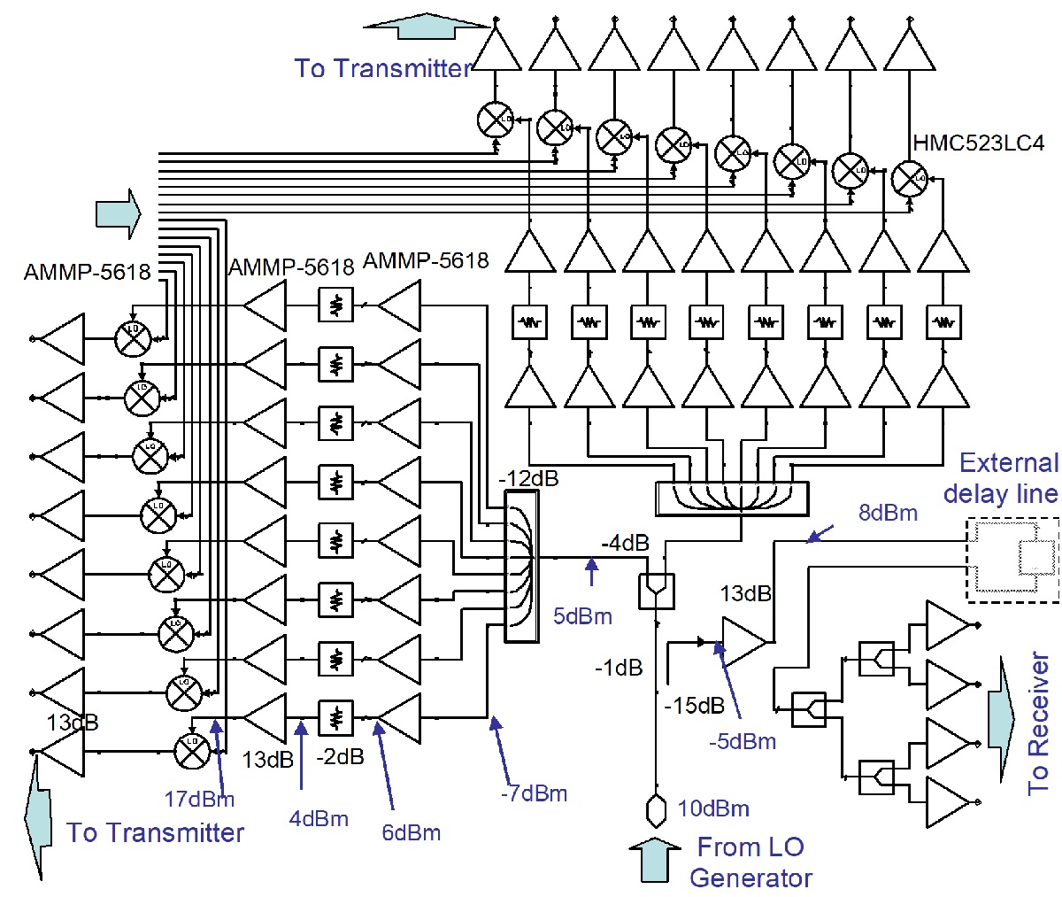
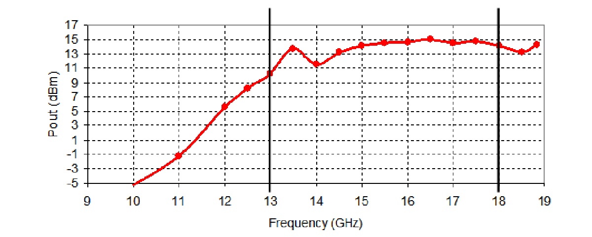
The imaging system uses several transmitting and receiving channels and is based on microwave distribution network. The network operates between 13GHz and 18GHz and provides 13 dBm output power. Using I/Q modulators in the transmit unit enables to identify each channel in the imaging array and hence perform the data acquisition of an image on all channels simultaneously.

Design
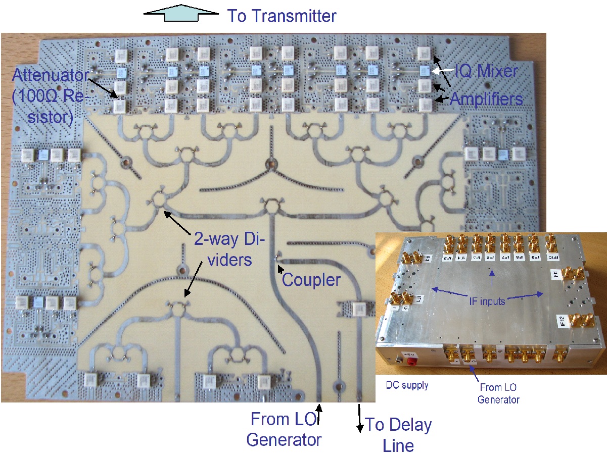
The circuit consists of a microwave directional coupler, power dividers, amplifiers, attenuators and I/Q modulators. The distribution unit also provides an option to connect an external delay line between the local oscillator and the power division network for the receiver.

The directional coupler is based on an asymmetric coupled-line section.
This type of coupler provides high coupling coefficient values (the ratio of the input power to the coupled power) and improved isolation in comparison to other realizations, such as branch-line couplers, tee power dividers, Wilkinson power dividers, rat-race couplers, and others. The measured coupling coefficient is approximately 15 dB, isolation is better than 22 dB, and return loss is better then 10 dB and 7 dB for the through and coupled ports respectively.

The power divider is based on a hybrid ring. The measured isolation of the divider is better than 16 dB. The input and output return losses are better than 8 dB and 10 dB for the input and output ports respectively. The measured insertion loss is around 1 dB.
Performance
The measured output return loss of the unit is approximately 10 dB. The measured output power of the transmitting channel is shown below. The distribution network operates in a frequency range from 13 GHz to 18 GHz.
