Supervised Projects
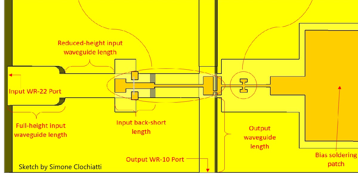
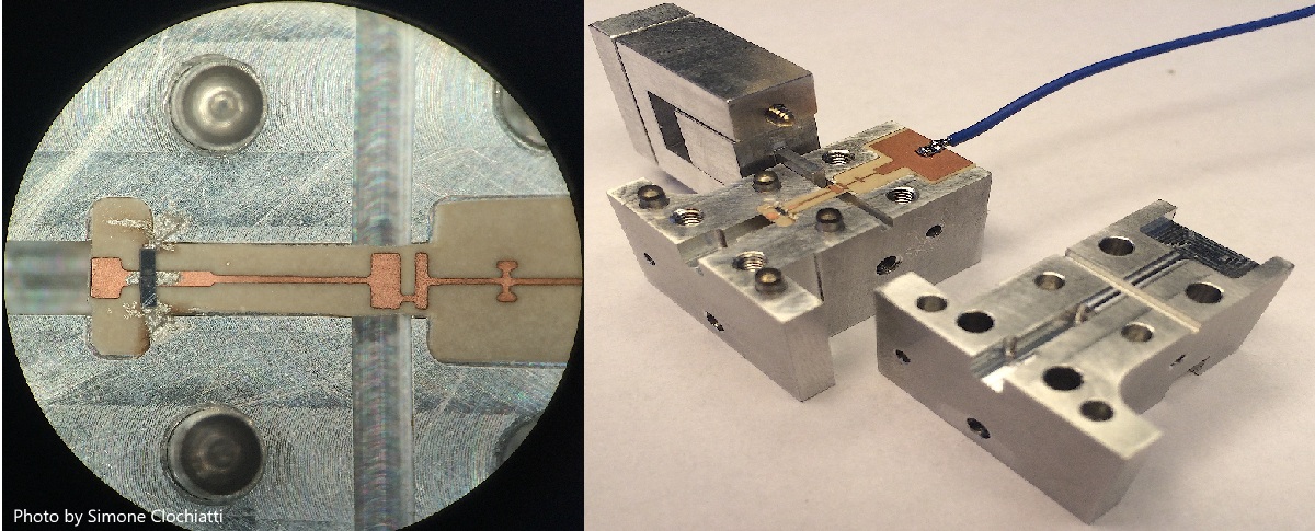
W-band frequency doubler with rectangular waveguide interface.
Motivation
The availability of fundamental tone sources in the millimeter-wave range is limited, which makes frequency multipliers an essential component in systems employing millimeter-wave signals.
Design
The doubler is based on MA46H146 varactor diode. Two
diodes in anti-series configuration is soldered on a planar PCB made with Rogers RT 6002 substrate (5
mil thickness). In general, for higher frequencies, a thinner substrate with a low dielectric
constant is desired, since the thickness of the substrate can become comparable to the
wavelength causing the propagation of unwanted modes and ultimately result in losses.
The height of the WR-22 rectangular waveguide, which is only 2.84mm, has limited the
number of diode chips that could be placed. In order to accommodate a minimum of two diodes, the reduced input waveguide
height transition is set to approximately the 60% of the WR-22 height.
Measurements
Measured output power is 1mW.
Microwave Transitions
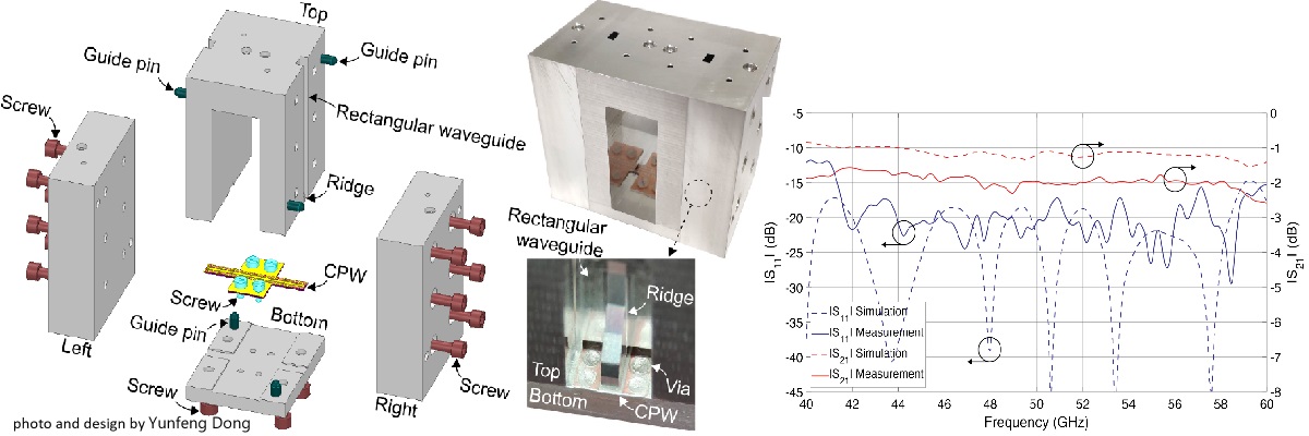
A rectangular waveguide to coplanar waveguide (CPW) transition at U-band (40–60 GHz).
Motivation
In millimeter wave range, rectangular waveguides have been widely used for system integration and packaging due to high power-handling capability, low transmission loss, and simple structure. The width and height of rectangular waveguides are mainly determined by the operating frequencies. Thus, with predefined dimensions for each frequency band, air-filled rectangular waveguides become standard interfaces for connecting different components and systems. However, the circuits and chips at such high frequencies still rely on planar structures. The transitions between rectangular waveguides and planar transmission lines, in particular, rectangular waveguide to CPW transitions are required.
Summary
The transition is based on a metal ridge inside the rectangular waveguide and applied to the CPW from top forming an orthogonal structure. The return loss is better than 12 dB at U-band with an insertion loss of less than 1.3 dB for each transition.
Further details
can be found in this .pdf: DOI: 10.23919/EuMC48046.2021.9338140
Antenna Arrays
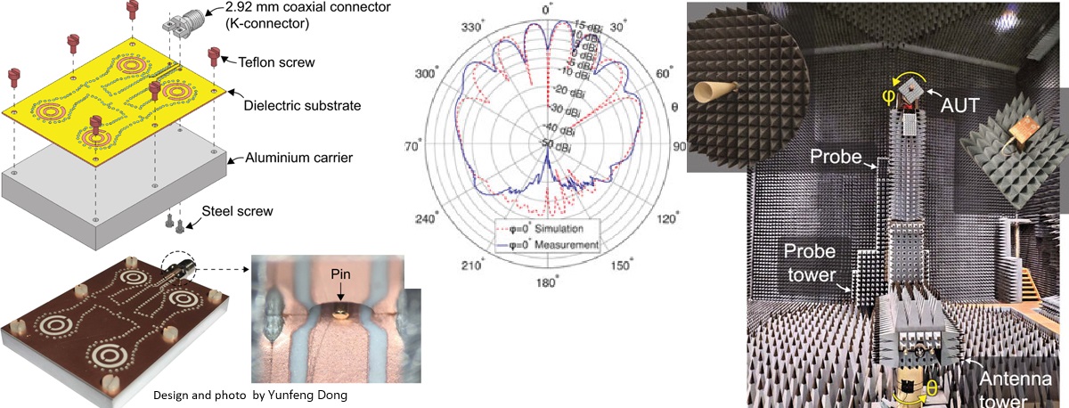
Wideband split-ring antenna arrays based on substrate integrated waveguide for Ka-band (26.5–40 GHz) applications.
Motivation
Design antennas for high-speed data transmissions.
Summary
The antenna array is fed by a 2.92mm coaxial connector (K-connector) and the power is equally distributed to each split-ring resonator. The coplanar waveguide (CPW), SIW, CPW-to-SIW transition, coaxial-to-CPW transition, and two-stage SIW power divider are designed. A thin Rogers 6002 substrate with silver epoxy-filled vias is used. A compact 2×2 antenna array is designed, fabricated, and tested. The measured directivity is 15.0 dBi with a fractional bandwidth of 23.0% centered at 30.5GHz.
Further details
can be found in this .pdf: https://doi.org/10.1017/S1759078721000684
Imaging Antenna
Fractionated Dipole Antenna for 7T MRI (298MHz).
Motivation
7T MRI is a promising modality for early detection of carotid plaques. Specialized antennas are required for imaging along with coilformers to hold the antennas close to the desired body area.
Design
The fractionated dipole antenna is printed on a RT/duroid 6002PTFE. The material has a low loss tangent, and is still flexible enoug to bend around the shape of the coilformer. A copper back plate is added on the fabricated antenna to reduce the electric field directed at the body. Symmetric matching network transforms impedance of the antenna to 50 ohms.
Performance
The imaging results above show the magnitude of the B-field through the neck phantom, and the coronal B1+ map. The yellow line represents the general outline of the coilformer. The antenna generates a consistent magnetic field along the antenna direction (yellow line).
Further details
can be found in this .pdf: DOI: 10.23919/EuMC48046.2021.9337985
Cable trap
Floating bazooka coaxial cable trap
Motivation
Cable traps aim to suppress common-mode currents in the transmission line. Multiple types of cable traps exist. Many of them are quite cumbersome and require stripping insulation and soldering directly to the cable. Within MR systems, it is not possible to use standard ferrite core cable traps, as their magnetic field interfere with the system. The floating cable trap introduces a solution to this. It is non-intrusive and can be tuned to the desired resonance frequency. The trap is a quarter-wave coaxial transmission line structure. This line is short-circuited on one side and open-circuited on the oposite side. The length can be shortened by connecting a capacitor on the open-circuited side. The inner conductor of the structure couples to the cable providing supression of the interfering signal.
Design
The floating cable trap is made up of three parts: a supporting insulator, a conductor, and capacitors for tuning. The supporting structure consists of two 3D printed splittable half cylinders. The surface is covered by a conductive material, usually copper. The dimensions of the cylinder determine the intrinsic inductance and capacitance of the cable trap, thus what Q-factor and rejection ratio will be possible to achieve. Depending on the design, multiple cables can also be fed through. It is also easy to move along the cable, as it does not have to be soldered onto the cable. In this way, it can quickly be placed in the most effective position along the cable. For the chosen here dimensions and 64MHz operation the capacitor value is in the range 180pF...190pF.

Performance
The measured rejection is in the range of 33 dB to 35 dB.
Further details
Cable trap 3D printed support .stl files .